
 EN
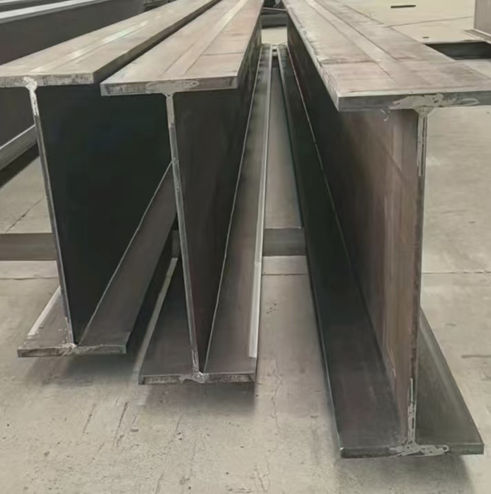
Structural Principles Governing Beam and Column Size Compatibility
Why Beam Depth Must Align with Column Flange Width for Efficient Moment Transfer
In rigid frame design, efficient moment transfer between beam and column hinges on geometric compatibility at the joint. The beam depth defines the internal lever arm for tension and compression flange forces; the column flange width provides the reaction surface for those forces. When the beam flange is significantly narrower than the column flange, load concentrates near the web—creating strain mismatch and increasing local stress. Conversely, if the beam is deeper than the column’s flange width, flexural prying develops in the column flange, reducing rotational stiffness and connection reliability. Ideal alignment places the beam flanges across the full width of the column flange, enabling direct force transfer via welds or bolts and minimizing secondary stresses. For bolted end-plate connections, the bolt gage must fit within the column flange width; an undersized beam forces the bolt group too close to the column web, compromising prying resistance. This geometric coordination ensures the beam’s full moment capacity can be safely resisted by the column flange—preventing local buckling, premature yield, and brittle fracture.
Connection Geometry and Load Path Continuity in Beam-and-Column Joints
Joint performance depends on a continuous, unbroken load path—directly shaped by member proportions. Whether using moment end plates, flange angles, or full-penetration welds, connection geometry must match both beam depth and column flange dimensions. Taller beams require extended end plates to distribute flange forces over a broader zone; narrow column flanges may need stiffeners to redirect tension into the column web without flange distortion. A deep-beam–slender-column mismatch introduces eccentricities that shift the neutral axis and amplify secondary moments in the column—often triggering brittle bearing failures at unbraced flange tips, as observed in full-scale cyclic tests. AISC 360–22 mitigates these risks by prescribing minimum flange thicknesses, bolt spacings, and weld sizes proportionate to connected members. Maintaining a direct force path—flange-to-flange, web-to-web—ensures ductile behavior and prevents the connection from becoming the weak link in the moment-resisting frame.
Practical Beam and Column Sizing Guidelines per AISC Standards
W-Shape Compatibility Tables: Matching Common Beam Sizes to Column Flange Widths (AISC 360–22)
Steel designers rely on AISC 360–22 Chapter J for verified checks of flange local bending and web crippling. A foundational rule is selecting a column whose flange width is at least equal to the beam flange width—this avoids excessive localized stress and simplifies detailing. For common W-shapes, the following pairings reflect industry-standard shop practice:
| Typical Beam (W‑Shape) | Compatible Column (Minimum Flange Width) | Notes |
|---|---|---|
| W12×26 | W8×31 (flange 8.0 in) | Suitable for light framing with simple shear connections. |
| W16×31 | W10×33 (flange 8.0 in) | Appropriate for moderate bays with bolted end-plate moment connections. |
| W18×40 | W12×40 (flange 8.0 in) | Recommended for long spans; verify column web stiffness. |
| W21×44 | W14×43 (flange 8.0 in) or wider | Typical for floor beams; continuity plates may enhance strength. |
These are minimum compatibilities; many designers upsize columns for drift control, constructability, or to simplify full-penetration welds. Always confirm connection strength and stability per AISC 360–22.
Rule-of-Thumb Ratios: Beam Depth vs. Column Depth and Flange Width
Before detailed analysis, experienced engineers apply proportionality checks to guide preliminary sizing. A widely adopted guideline sets beam depth between 50% and 60% of column depth for interior bays—though exceptions exist when flange widths align well (e.g., W21×44 beam on W14×90 column yields a 0.68 depth ratio but remains viable due to compatible 8.0-in flanges). Crucially, the beam flange width must never exceed the column flange width, with a maximum ratio of 0.90 considered safe. For fully restrained moment frames, a ratio below 0.80 improves force transfer and often eliminates the need for column flange stiffeners. Additionally, the column web thickness should exceed the beam flange thickness to prevent web crippling or buckling under concentrated flange forces. These rules streamline early-stage design and help avoid costly revisions later.
Real-World Consequences of Mismatched Beam and Column Sizes
A failure to coordinate beam depth with column flange width transforms the joint into a stress concentrator—with consequences extending far beyond serviceability. A recent mid-rise retrofit illustrates the cascading impact of this oversight.
Case Study: Connection Stress Failure in a Mid-Rise Retrofit Due to Beam-and-Column Proportion Mismatch
During a major renovation of a 12-story urban commercial building, two new levels were added while retaining existing W14×90 columns—each with a 10-inch flange width. To accommodate increased floor loads, the design specified deeper W21×55 beams (depth = 21.0 in). After 18 months of service, hairline fatigue cracks appeared at multiple beam-to-column moment connections, accompanied by visible joint rotation. Finite-element analysis confirmed that the beam depth exceeded the column flange width by more than 100%, forcing moment transfer onto a narrow, overstressed bearing area. Emergency shoring was installed, and remediation—including field-welded stiffener plates and re-engineered end plates—cost over $1.2 million. The post-failure review cited a violation of AISC 360–22 Commentary Section J10.2, which advises that for fully restrained connections, beam depth should not exceed 1.5 times the column flange width. This case underscores how a seemingly minor proportion mismatch—overlooked during schematic design—can escalate into a life-safety concern and a multimillion-dollar correction.
Innovations Redefining Beam and Column Size Relationships
Slim-Floor Systems and Hybrid Columns: New Constraints and Opportunities for Beam-and-Column Integration
Emerging systems like slim-floor construction and hybrid columns challenge traditional size compatibility logic. Slim-floor systems partially embed beams within the slab, reducing story height—but also decouple beam depth from column flange width, disrupting the conventional lever-arm geometry needed for efficient moment transfer. Similarly, hybrid columns—such as concrete-filled steel tubes or steel–concrete composites—enable slimmer profiles yet introduce stiffness mismatches that complicate load path continuity. In both cases, shallow beam flanges may fail to fully engage the column’s moment capacity, risking discontinuous force flow and premature connection failure. Yet these innovations offer compelling advantages: longer clear spans, reduced structural steel tonnage, and lower embodied carbon. Their adoption demands updated connection detailing—such as extended continuity plates, enhanced stiffening, or alternative anchorage strategies—and signals a shift toward performance-based compatibility criteria rather than fixed dimensional ratios. As low-carbon construction accelerates, beam–column integration will increasingly prioritize system-level behavior over isolated member proportions.
Frequently Asked Questions
Why is beam depth alignment with column flange width crucial?
Beam depth alignment ensures efficient moment transfer and reduces local stress by enabling direct force transfer through welds or bolts without causing strain mismatches or flexural prying.
What are AISC guidelines for beam-column compatibility?
AISC 360–22 recommends aligning beam flange width with column flange width, using proportional depth ratios, and ensuring column web thickness exceeds beam flange thickness to prevent web crippling.
What is the impact of mismatched beam-column proportions?
Mismatched proportions result in stress concentrations, reduced joint reliability, potential brittle failures, and additional corrective costs, as exemplified in the mid-rise retrofit case study.
What innovations are reshaping beam-column compatibility?
Slim-floor systems and hybrid columns are introducing new constraints while offering advantages like reduced height and steel tonnage. They require updated detailing and performance-based compatibility standards.