
 EN
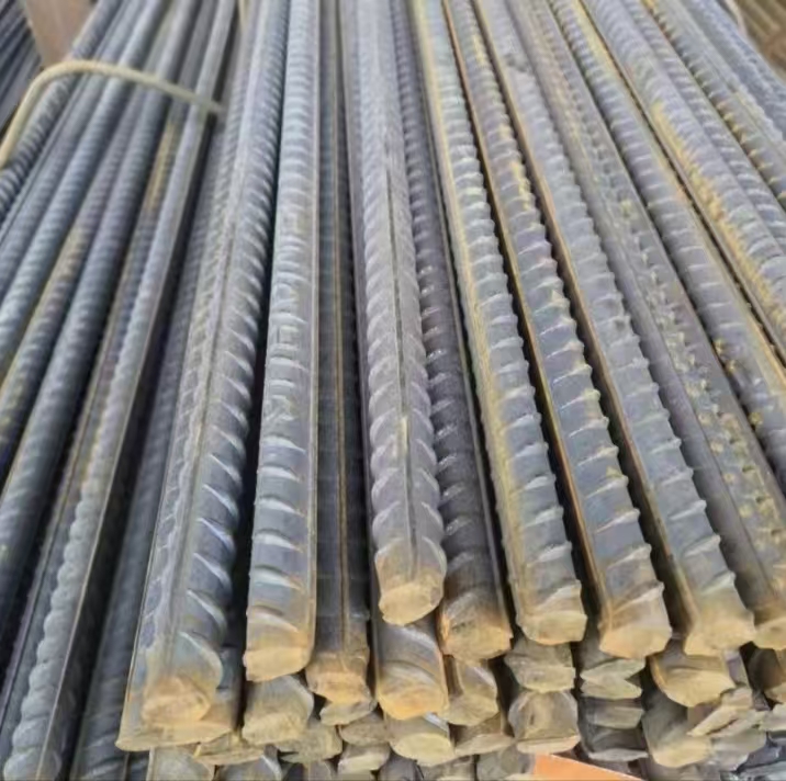
Fundamental Design Methods for Steel Beam and Column Capacity
ASD vs. LRFD: Strength-based and serviceability implications for beam and column design
Designers historically used Allowable Strength Design (ASD), applying a single factor of safety to material strengths. Modern codes adopt Load and Resistance Factor Design (LRFD), which explicitly separates uncertainties in loads and resistance through distinct factors. For beam and column members, LRFD typically yields more efficient (lighter) sections under variable or extreme loading, while ASD remains intuitive for serviceability checks like deflection—since it uses unfactored service loads.
| Aspect | ASD | LRFD |
|---|---|---|
| Basis | Deterministic, single factor of safety | Probabilistic, separate load and resistance factors |
| Load combinations | Service loads (e.g., D+L) | Factored loads (e.g., 1.2D+1.6L) |
| Strength reduction | Ω (safety factor) > 1 | φ (resistance factor) < 1 |
| Reliability target | Implicit | Explicit β ≈ 3.0 (AISC 360‑22) |
| Material overstrength | Not directly accounted | Reflected in φ factor |
LRFD’s higher load factors—especially for snow, seismic, and wind—better represent low-probability, high-consequence events, while its φ factors incorporate material variability, residual stresses, and geometric imperfections (AISC 360‑22). This results in more uniform reliability across load types. In contrast, ASD’s uniform safety factor can be overly conservative for dead-load-dominated members but insufficiently protective for live- or event-load-dominated cases. For columns, both methods treat slenderness similarly, but LRFD’s φ values more explicitly account for initial crookedness and residual stresses. For beams, lateral-torsional buckling equations are identical—but LRFD’s factored moments increase required flexural capacity by ~20–30% compared to ASD for live-load-dominated spans. Serviceability checks remain load-level dependent; however, LRFD’s designated service-load combinations (e.g., D+L) ensure deflection limits are met without unnecessary conservatism. In practice, many engineers cross-check both methods—particularly for complex or critical structures—to confirm both strength and serviceability compliance.
When finite element analysis (FEA) becomes necessary for complex beam and column systems
While code-based methods are sufficient for regular, prismatic frames with standard connections, finite element analysis (FEA) becomes essential when geometry, loading, or boundary conditions exceed simplified assumptions. FEA is warranted for non-prismatic members (e.g., tapered beams), built-up columns with irregular configurations, or members with localized reinforcements such as gusset plates and stiffeners—where stress concentrations and non-uniform strain distributions invalidate standard section property assumptions. Second-order P-Δ and P-δ effects also demand geometric nonlinear analysis in slender or laterally flexible frames, where traditional first-order methods underestimate member forces and drift. For dynamic loads—including seismic and wind-induced vibrations—modal and time-history analyses provide accurate assessments of global response, member demands, and interstory drift. Local buckling under combined axial and flexural loading requires shell-element modeling to capture flange/web instability modes not resolved by AISC’s nominal strength equations. FEA further enables fire-resistance evaluation, incorporating temperature-dependent steel properties and thermal expansion effects that drive progressive collapse mechanisms. In these scenarios, FEA does not replace code compliance—it reveals hidden demand-capacity ratios and informs targeted, safer, and often more economical designs.
Key Structural Parameters Governing Beam and Column Capacity
Section geometry, slenderness, and material grade: How Iₓ, Zₓ, Kₗ/r, and F_y jointly determine capacity
Steel beam and column capacity emerges from the interplay of section geometry, slenderness, and material strength. The moment of inertia Iₓ governs bending stiffness and deflection behavior; the plastic section modulus Zₓ sets the theoretical full-plastic moment capacity Mₚ = F_y × Zₓ. Increasing section depth generally improves both Iₓ and Zₓ, reducing service deflections and raising ultimate flexural strength. For columns, the effective slenderness ratio Kₗ/r—where K is the effective length factor, L the unbraced length, and r the radius of gyration—controls buckling susceptibility. As Kₗ/r increases, the critical buckling stress drops sharply, shifting failure mode from yielding to elastic or inelastic buckling well below F_y. While yield strength F_y defines the upper bound of material resistance, its practical contribution is limited by local buckling (governed by flange/web slenderness) and global instability. For example, a compact wide-flange beam with high F_y and Zₓ may achieve full plastic moment, whereas an otherwise identical column with high Kₗ/r may buckle at less than half F_y. Thus, capacity is not dictated by any single parameter—but by how Iₓ, Zₓ, Kₗ/r, and F_y interact within the context of cross-section classification and stability limits. AISC 360-22 codifies this relationship through unified nominal strength equations for flexure and compression, ensuring consistent reliability across member types and applications.
Load Combination Effects on Beam and Column Performance
Dead, live, snow, and seismic loads: Impacts on axial, flexural, and interaction demands
Dead loads (D) impose constant axial compression and bending if eccentrically applied. Live loads (L) introduce variable flexural demand—and, in multi-story frames, can increase axial force in supporting columns. Snow loads (S), especially in high-elevation or northern regions, add substantial gravity load that frequently governs roof beam and column sizing. Seismic loads (E) produce lateral forces that induce axial tension/compression reversals and large bending moments, particularly in moment frames and braced bays. When combined per ASCE 7-22 strength design combinations—such as 1.2D + 1.6L + 0.5S or 1.2D + 1.0E + L + 0.2S—the resulting axial force (Pᵣ) and bending moments (Mᵣₓ, Mᵣᵧ) act simultaneously, creating biaxial P-M interaction demands. AISC 360-22 Chapter H interaction equations (H1-1a/b) verify that the combined stress ratio remains ≤ 1.0, accounting for second-order effects and member stability. Without proper load combination analysis, a beam designed solely for bending may fail under added axial compression, or a column sized for pure axial load may buckle prematurely when subjected to combined flexure. Overlooking realistic multi-hazard load interactions risks under-designed members that compromise structural integrity under actual service conditions.
Code-Driven Verification: AISC 360-22 and IBC Compliance for Beam and Column Systems
AISC Chapter H interaction equations for beam-column members in braced and unbraced frames
Chapter H of AISC 360-22 provides the governing framework for verifying beam-column members subject to combined axial and flexural loading. The primary interaction equation—H1-1a for doubly symmetric members—is:
Pr/Pc + (8/9)[(Mrx/Mcx) + (Mry/Mcy)] ≤ 1.0
This expression evaluates the combined demand-to-capacity ratio, calibrated to reflect second-order P-δ and P-Δ effects inherent in real frame behavior. In braced frames, lateral stability reduces the effective length factor (K) toward 1.0, simplifying slenderness assessment and minimizing amplification of flexural demand. In unbraced frames, K exceeds 1.0 and must be determined rigorously—either via alignment charts or, preferably, direct analysis per AISC 360-22’s updated guidance. The 2022 edition emphasizes direct analysis as the default method for moment frames, eliminating reliance on approximate K-value assumptions and improving accuracy in predicting frame instability. Engineers must apply this equation to all applicable load combinations; exceeding unity indicates insufficient capacity under that demand set and triggers redesign—whether through larger sections, added bracing, or revised framing strategies.
IBC 2021 regional provisions (e.g., Utah snow loads) and their influence on beam and column sizing
The 2021 International Building Code (IBC) does not prescribe member capacities—but it mandates the environmental load magnitudes that drive AISC 360-22 verification. Regional variations have profound implications: ground snow load, for instance, ranges from ~20 psf in southern climates to over 200 psf in high-elevation Utah counties—per IBC-referenced state amendments. This directly escalates both axial (Pᵣ) and flexural (Mᵣ) demands in roof beams and supporting columns, especially in low-rise or long-span structures. Further, the IBC ties snow load importance to risk category—raising design values up to 20% for essential facilities like hospitals or emergency centers. Consequently, a beam-column system sized for a generic 30 psf snow load would be critically under-designed for a Utah mountain site, even though the same AISC equations apply. The design process thus follows a strict compliance chain: IBC establishes the load magnitude; AISC 360-22 determines the capacity check. Ignoring this linkage risks unsafe designs that meet neither code’s intent nor real-world performance expectations.
Frequently Asked Questions (FAQ)
What is the primary difference between ASD and LRFD?
The key difference is that ASD uses a single safety factor applied to material strengths, while LRFD separates load and resistance uncertainties with distinct factors, typically resulting in more efficient designs under variable loads.
When is finite element analysis (FEA) necessary for steel beams and columns?
FEA becomes necessary for irregular configurations, localized reinforcements, or when standard assumptions fail—such as with tapered beams or dynamic load scenarios (e.g., seismic effects).
What governs the design strength of steel beams and columns?
The design strength depends on parameters like section geometry (Iₓ, Zₓ), material grade (Fₓ), and slenderness (Kₗ/r ratio), which together determine the interaction of deflection, strength, and stability.
How do load combinations impact beam and column performance?
Load combinations predict realistic demand scenarios (e.g., 1.2D + 1.6L), ensuring that combined axial and flexural stresses do not exceed design limits under applicable hazardous conditions.
What role does the International Building Code (IBC) play in steel design?
IBC provides regional environmental load requirements (e.g., snow, wind) that are then verified against AISC 360-22 capacity equations to ensure safe designs.
Table of Contents
- Fundamental Design Methods for Steel Beam and Column Capacity
- Key Structural Parameters Governing Beam and Column Capacity
- Load Combination Effects on Beam and Column Performance
- Code-Driven Verification: AISC 360-22 and IBC Compliance for Beam and Column Systems
-
Frequently Asked Questions (FAQ)
- What is the primary difference between ASD and LRFD?
- When is finite element analysis (FEA) necessary for steel beams and columns?
- What governs the design strength of steel beams and columns?
- How do load combinations impact beam and column performance?
- What role does the International Building Code (IBC) play in steel design?