
 EN
EN
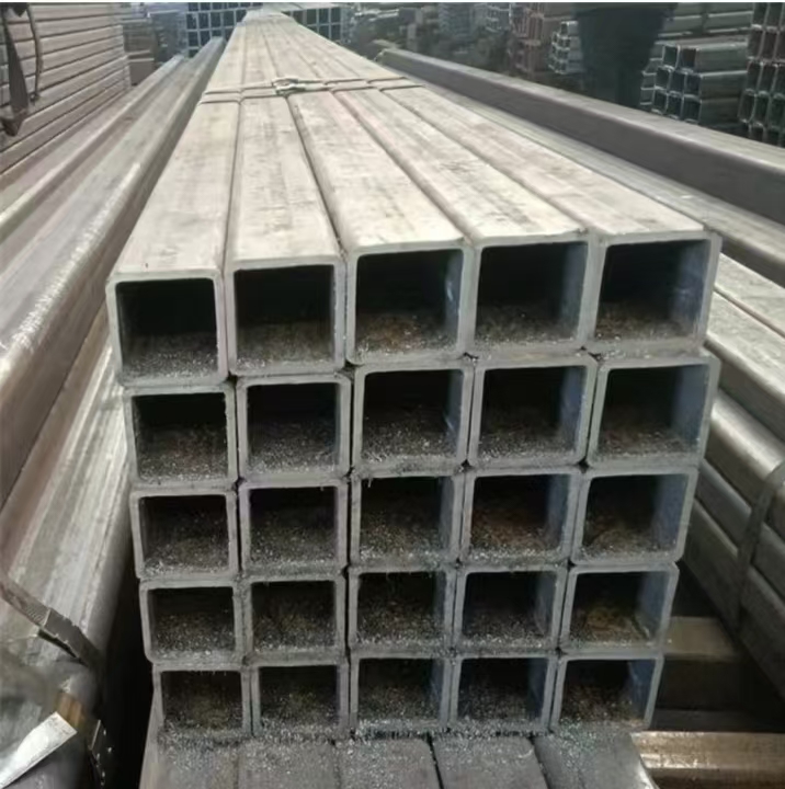
Beam and Column Fundamentals: Roles, Types, and Load-Bearing Logic
Understanding the distinct roles of beams and columns is the foundation of safe commercial building design. Columns are vertical load-bearing members that carry axial compressive forces—from beams, slabs, and upper floors—down to the footings. Beams, in contrast, act as horizontal flexural members that resist bending moments and transfer floor and roof loads laterally to the columns. This defined load path—slab → beam → column → footing—requires each element to be sized and detailed with precision. A column’s dominant failure mode is buckling under compression; beam design, however, is governed by bending stress and serviceability limits like deflection.
Common steel column sections include wide-flange (W) shapes, hollow structural sections (HSS), and built-up box members. Steel beams are typically I-shaped or wide-flange sections, with depth-to-span ratios ranging from L/20 to L/24 for floor systems and L/24 to L/30 for lighter roof applications. In reinforced concrete, columns are proportioned for combined axial load and moment, while beams are designed primarily for flexure and shear. The tributary area method offers a practical way to estimate gravity loads: for example, an interior column in a 4 m × 4 m grid may carry approximately 34 kN per floor when dead and live loads are combined. Because interior columns bear significantly more load than edge or corner columns, accurate load calculation is essential—not just for safety, but to avoid overdesign and unnecessary material use. A clear grasp of how beams and columns interact ensures structural integrity, serviceability, and long-term performance across decades of building life.
Design Considerations for Beam and Column Integration in Steel and Concrete Frames
Integrating beams and columns into a unified structural frame requires careful coordination of material behavior, load paths, and stability constraints. Each material responds differently to combined bending and axial stresses—and section proportions directly influence overall frame efficiency, stiffness, and constructability.
Material-Specific Behavior Under Bending and Axial Loads
Structural steel and reinforced concrete exhibit fundamentally different stress–strain responses. Steel’s isotropic, linear-elastic behavior allows slender, efficient sections—but local buckling in compression flanges must be verified. Reinforced concrete, by contrast, is inherently nonlinear: concrete resists compression, while steel reinforcement carries tension. Under combined bending and axial force, concrete columns follow direction-dependent interaction diagrams, whereas steel members behave more symmetrically. Additionally, time-dependent effects like creep and shrinkage in concrete require special consideration in long-term deflection and service-load combinations—factors not present in steel design.
Span-to-Depth Ratios and Slenderness Limits for Stability
Preliminary sizing relies on empirically validated span-to-depth ratios to control deflection and vibration. For simply supported steel beams, typical ratios range from L/20 to L/30; reinforced concrete beams generally require deeper sections, with ratios between L/12 and L/18. Continuous beams allow a 10–15% relaxation of these limits due to moment redistribution. Column stability hinges on slenderness: AISC 360-22 permits a maximum effective slenderness ratio (kL/r) of 200 for steel columns, while ACI 318-19 restricts unsupported length-to-depth ratios to 100 for non-sway concrete frames. Exceeding these thresholds triggers second-order (P-Δ) analysis and moment magnification—adding significant complexity to design. A balanced approach ensures serviceability and safety without overspending on material or detailing.
Beam and Column Connection Methods: Performance, Code Compliance, and Constructability
The performance of any beam–column frame depends critically on how forces—shear, moment, and axial load—are transferred at the joints. Connection selection influences global stability, erection speed, and long-term durability. Design must reconcile strength demands with real-world constraints like fabrication cost, field access, and inspection feasibility. The following subsections explain how joint classification guides structural modeling and outline standard detailing practices aligned with current codes.
Rigid, Pinned, and Semi-Rigid Joint Implications for Frame Analysis
Connection classification determines the analytical model applied to the entire structure. A pinned connection transfers only vertical shear, permitting free rotation and simplifying analysis to a statically determinate system. A rigid moment connection transfers both shear and bending moment, suppressing relative rotation and resulting in a statically indeterminate frame requiring advanced analysis. Semi-rigid connections reflect actual field behavior—providing partial moment resistance and rotational stiffness—and must be modeled explicitly using moment-rotation curves. Misclassifying a semi-rigid joint as fully pinned or rigid leads to unconservative drift predictions or overly conservative member forces, affecting both structural safety and economy.
Common Detailing Practices per AISC and ACI Standards
AISC 360-22 detailing emphasizes ductility, redundancy, and a clear load path. Shear connections—such as bolted shear tabs or seated connections—are widely used for their simplicity and speed of erection. Moment-resisting frames commonly employ welded flange plates or bolted extended end plates, often with coped beam webs for fit-up and alignment. Under ACI 318-19, concrete frame detailing prioritizes joint confinement and bar anchorage: closely spaced transverse ties within the beam-column joint core prevent brittle shear failure and ensure adequate development length for longitudinal reinforcement. Standard hooks, headed bars, and controlled bar spacing mitigate congestion—especially critical where beam and column reinforcement intersect. Joint integrity is not incidental; it is central to the frame’s robustness and seismic resilience.
Optimizing Beam and Column Layouts for Cost, Space, and Future Flexibility
Optimizing beam and column layouts is a strategic decision—not just an engineering one—that balances initial cost, spatial efficiency, and adaptability over the building’s lifecycle. Data-driven design can reduce structural material costs by up to 15% per floor, shifting emphasis from uniform over-sizing to zone-specific tailoring of beam depths and column spacing. In steel-frame commercial buildings, bay spacing is the most influential cost lever: it affects both primary frame weight and secondary member requirements (e.g., purlins, joists). As shown below, a 20–25 ft (6–7.6 m) bay consistently delivers optimal value.
| Bay Spacing | Frame Cost | Purlin Cost | Total Cost |
|---|---|---|---|
| 15 ft | Higher | Lower | Higher |
| 20 ft | Optimal | Optimal | Minimum |
| 25 ft | Lower | Higher | Near minimum |
| 30 ft | Lower | Much higher | Higher |
Cost-efficient layouts also improve functional space. Regular column grids and shallower beams in office zones preserve ceiling height and HVAC clearance, while clear-span configurations in loading docks or open-plan floors eliminate operational obstructions. For future flexibility, a modular, repeatable column grid enables seamless expansion—allowing new bays to align precisely with existing framing. This avoids costly rework, minimizes tenant disruption, and supports evolving uses—from warehouse automation upgrades to adaptive reuse. Aligning beam and column decisions with both current loads and long-term adaptability ensures the building remains operationally viable and economically sound across its full service life.
FAQ
What are the primary roles of beams and columns?
Beams are horizontal flexural members that resist bending moments and transfer floor and roof loads laterally to columns. Columns are vertical load-bearing members that carry axial forces down to the footings.
Why is accurate load calculation important for columns?
Accurate load calculation prevents overdesign, reduces material use, ensures safety, and accounts for varied load-bearing demands across interior, edge, and corner columns.
How do steel and concrete differ in beam and column design?
Steel exhibits linear-elastic behavior, allowing efficient slender sections, while concrete resists compression and relies on steel reinforcement for tension. Both materials have specific design limits and long-term performance considerations.
What span-to-depth ratios are recommended for beams?
Steel beams typically utilize ratios between L/20 to L/30, whereas reinforced concrete beams use deeper sections with ratios ranging from L/12 to L/18.
Why is joint detailing important in beam-column frames?
Proper joint detailing ensures strength, ductility, redundancy, and long-term durability, while also providing resilience against brittle shear failures and seismic events.
Table of Contents
- Beam and Column Fundamentals: Roles, Types, and Load-Bearing Logic
- Design Considerations for Beam and Column Integration in Steel and Concrete Frames
- Beam and Column Connection Methods: Performance, Code Compliance, and Constructability
- Optimizing Beam and Column Layouts for Cost, Space, and Future Flexibility
- FAQ